This page is under construction. It will be based on this page.
External vertices
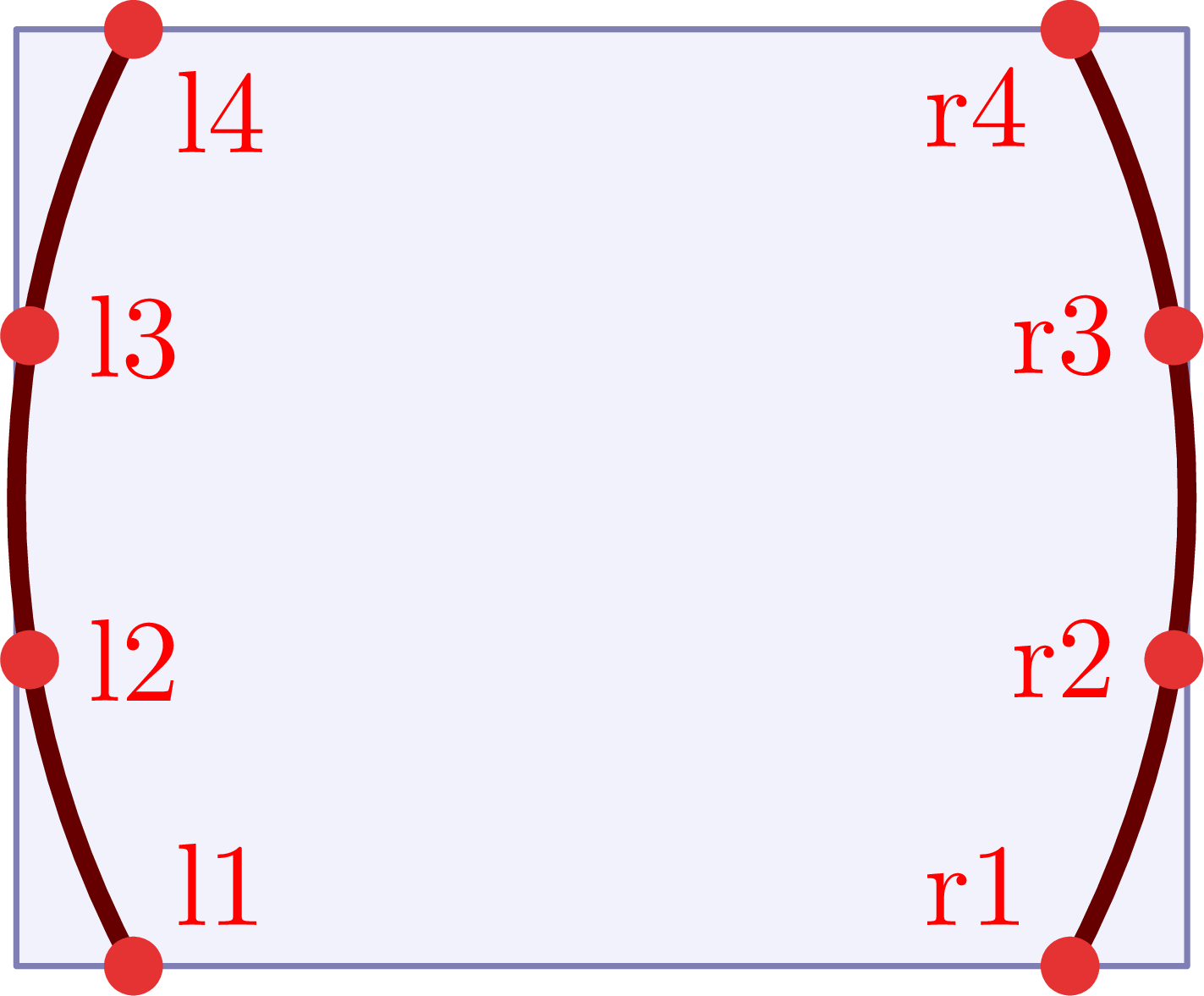
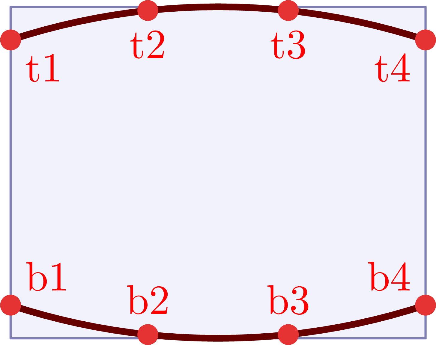
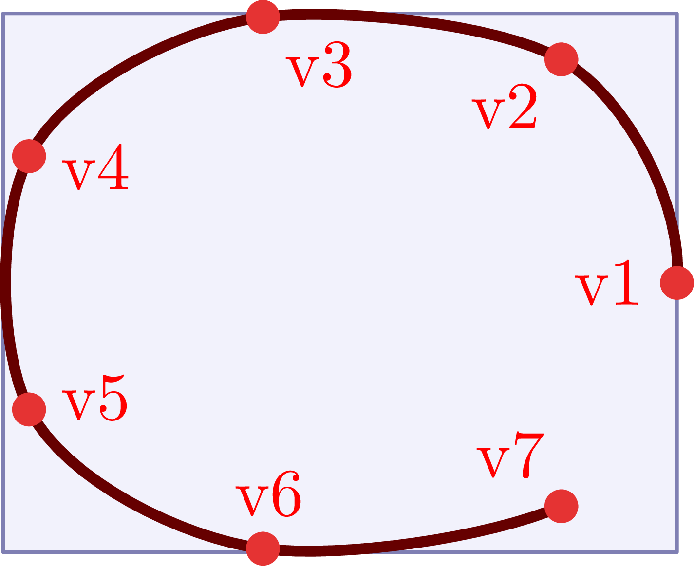
It is easy to define the external vertices in feynmp by using one or more these five commands:
\fmfleft,\fmfright,\fmftop,\fmfbottom,\fmfsurround.
For example:
\documentclass[11pt,border=4pt]{standalone}
\usepackage{feynmp-auto}
\begin{document}
\begin{fmffile}{feyngraph}
  \begin{fmfgraph*}(100,80) % dimensions (WH)
    \fmfcurved % redundant
    % define external vertices
    \fmfleft{l1,l2,l3,l4}
    \fmfright{r1,r2,r3,r4}
    % draw circles at points with labels
    \fmfv{d.sh=circle,d.f=full,d.si=4,l.d=5,label=l1,l.a=45}{l1}
    \fmfv{d.sh=circle,d.f=full,d.si=4,l.d=5,label=l2,l.a=0}{l2}
    \fmfv{d.sh=circle,d.f=full,d.si=4,l.d=5,label=l3,l.a=0}{l3}
    \fmfv{d.sh=circle,d.f=full,d.si=4,l.d=5,label=l4,l.a=-45}{l4}
    \fmfv{d.sh=circle,d.f=full,d.si=4,l.d=5,label=r1,l.a=135}{r1}
    \fmfv{d.sh=circle,d.f=full,d.si=4,l.d=5,label=r2,l.a=180}{r2}
    \fmfv{d.sh=circle,d.f=full,d.si=4,l.d=5,label=r3,l.a=180}{r3}
    \fmfv{d.sh=circle,d.f=full,d.si=4,l.d=5,label=r4,l.a=-135}{r4}
  \end{fmfgraph*}
\end{fmffile}
\end{document}
\documentclass[11pt,border=4pt]{standalone}
\usepackage{feynmp-auto}
\begin{document}
\begin{fmffile}{feyngraph}
\begin{fmfgraph*}(100,80) % dimensions (WH)
\fmfcurved % redundant
% define external vertices
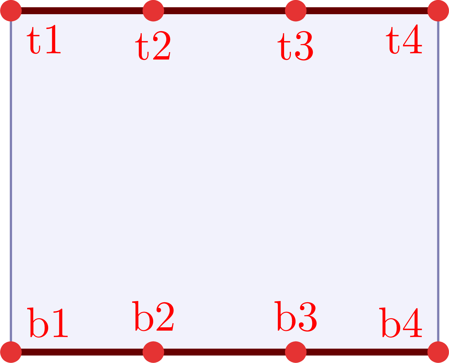
\fmftop{t1,t2,t3,t4}
\fmfbottom{b1,b2,b3,b4}
% draw circles at points with labels
\fmfv{d.sh=circle,d.f=full,d.si=4,l.d=5,label=t1,l.a=-45}{t1}
\fmfv{d.sh=circle,d.f=full,d.si=4,l.d=5,label=t2,l.a=-90}{t2}
\fmfv{d.sh=circle,d.f=full,d.si=4,l.d=5,label=t3,l.a=-90}{t3}
\fmfv{d.sh=circle,d.f=full,d.si=4,l.d=5,label=t4,l.a=-135}{t4}
\fmfv{d.sh=circle,d.f=full,d.si=4,l.d=5,label=b1,l.a=45}{b1}
\fmfv{d.sh=circle,d.f=full,d.si=4,l.d=5,label=b2,l.a=90}{b2}
\fmfv{d.sh=circle,d.f=full,d.si=4,l.d=5,label=b3,l.a=90}{b3}
\fmfv{d.sh=circle,d.f=full,d.si=4,l.d=5,label=b4,l.a=135}{b4}
\end{fmfgraph*}
\end{fmffile}
\end{document}
\documentclass[11pt,border=4pt]{standalone}
\usepackage{feynmp-auto}
\begin{document}
\begin{fmffile}{feyngraph}
\begin{fmfgraph*}(100,80) % dimensions (WH)
\fmfcurved % redundant
% define external vertices
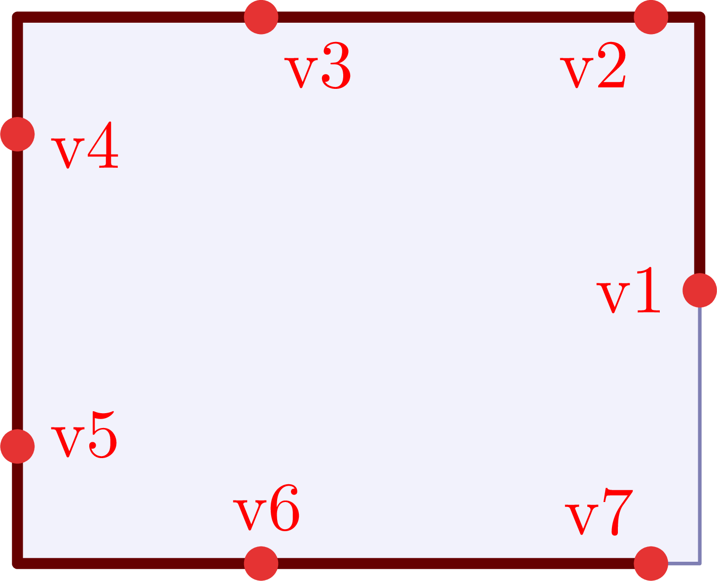
\fmfsurround{v1,v2,v3,v4,v5,v6,v7}
% draw circles at points with labels
\fmfv{d.sh=circle,d.f=full,d.si=4,l.d=5,label=v1,l.a=180}{v1}
\fmfv{d.sh=circle,d.f=full,d.si=4,l.d=5,label=v2,l.a=-130}{v2}
\fmfv{d.sh=circle,d.f=full,d.si=4,l.d=5,label=v3,l.a=-50}{v3}
\fmfv{d.sh=circle,d.f=full,d.si=4,l.d=5,label=v4,l.a=-20}{v4}
\fmfv{d.sh=circle,d.f=full,d.si=4,l.d=5,label=v5,l.a=20}{v5}
\fmfv{d.sh=circle,d.f=full,d.si=4,l.d=5,label=v6,l.a=80}{v6}
\fmfv{d.sh=circle,d.f=full,d.si=4,l.d=5,label=v7,l.a=120}{v7}
\end{fmfgraph*}
\end{fmffile}
\end{document}
The external vertices are by default positioned on a curve. One can set this behavior explicitly with \fmfcurved, In code example above it is redundant, but it can be used if one wants to turn off the behavior of \fmfstraight (see next) in the same diagram.
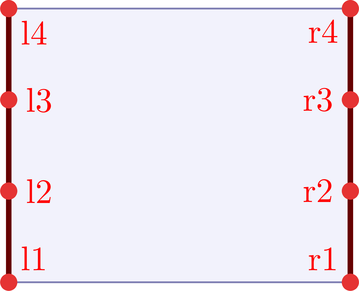
One can set the external vertices on a straight line along the edges for the rectangular frame with \fmfstraight instead. Below is an illustration of \fmfstraight.
\documentclass[11pt,border=4pt]{standalone}
\usepackage{feynmp-auto}
\begin{document}
\begin{fmffile}{feyngraph}
  \begin{fmfgraph*}(100,80) % dimensions (WH)
    \fmfstraight
    % define external vertices
    \fmfleft{l1,l2,l3,l4}
    \fmfright{r1,r2,r3,r4}
    % draw circles at points with labels
    \fmfv{d.sh=circle,d.f=full,d.si=4,l.d=5,label=l1,l.a=45}{l1}
    \fmfv{d.sh=circle,d.f=full,d.si=4,l.d=5,label=l2,l.a=0}{l2}
    \fmfv{d.sh=circle,d.f=full,d.si=4,l.d=5,label=l3,l.a=0}{l3}
    \fmfv{d.sh=circle,d.f=full,d.si=4,l.d=5,label=l4,l.a=-45}{l4}
    \fmfv{d.sh=circle,d.f=full,d.si=4,l.d=5,label=r1,l.a=135}{r1}
    \fmfv{d.sh=circle,d.f=full,d.si=4,l.d=5,label=r2,l.a=180}{r2}
    \fmfv{d.sh=circle,d.f=full,d.si=4,l.d=5,label=r3,l.a=180}{r3}
    \fmfv{d.sh=circle,d.f=full,d.si=4,l.d=5,label=r4,l.a=-135}{r4}
  \end{fmfgraph*}
\end{fmffile}
\end{document}
\documentclass[11pt,border=4pt]{standalone}
\usepackage{feynmp-auto}
\begin{document}
\begin{fmffile}{feyngraph}
  \begin{fmfgraph*}(100,80) % dimensions (WH)
    \fmfstraight
    % define external vertices
    \fmftop{t1,t2,t3,t4}
    \fmfbottom{b1,b2,b3,b4}
    % draw circles at points with labels
    \fmfv{d.sh=circle,d.f=full,d.si=4,l.d=5,label=t1,l.a=-45}{t1}
    \fmfv{d.sh=circle,d.f=full,d.si=4,l.d=5,label=t2,l.a=-90}{t2}
    \fmfv{d.sh=circle,d.f=full,d.si=4,l.d=5,label=t3,l.a=-90}{t3}
    \fmfv{d.sh=circle,d.f=full,d.si=4,l.d=5,label=t4,l.a=-135}{t4}
    \fmfv{d.sh=circle,d.f=full,d.si=4,l.d=5,label=b1,l.a=45}{b1}
    \fmfv{d.sh=circle,d.f=full,d.si=4,l.d=5,label=b2,l.a=90}{b2}
    \fmfv{d.sh=circle,d.f=full,d.si=4,l.d=5,label=b3,l.a=90}{b3}
    \fmfv{d.sh=circle,d.f=full,d.si=4,l.d=5,label=b4,l.a=135}{b4}
  \end{fmfgraph*}
\end{fmffile}
\end{document}
\documentclass[11pt,border=4pt]{standalone}
\usepackage{feynmp-auto}
\begin{document}
\begin{fmffile}{feyngraph}
  \begin{fmfgraph*}(100,80) % dimensions (WH)
    \fmfstraight
    % define external vertices
    \fmfsurround{v1,v2,v3,v4,v5,v6,v7}
    % draw circles at points with labels
    \fmfv{d.sh=circle,d.f=full,d.si=4,l.d=5,label=v1,l.a=180}{v1}
    \fmfv{d.sh=circle,d.f=full,d.si=4,l.d=5,label=v2,l.a=-130}{v2}
    \fmfv{d.sh=circle,d.f=full,d.si=4,l.d=5,label=v3,l.a=-50}{v3}
    \fmfv{d.sh=circle,d.f=full,d.si=4,l.d=5,label=v4,l.a=-20}{v4}
    \fmfv{d.sh=circle,d.f=full,d.si=4,l.d=5,label=v5,l.a=20}{v5}
    \fmfv{d.sh=circle,d.f=full,d.si=4,l.d=5,label=v6,l.a=80}{v6}
    \fmfv{d.sh=circle,d.f=full,d.si=4,l.d=5,label=v7,l.a=120}{v7}
  \end{fmfgraph*}
\end{fmffile}
\end{document}
Tension
Below is a simple example of how one can use tension to make lines between vertices shorter (tension>1) or longer (tension<1). The default tension is 1.
\documentclass[11pt,border=4pt]{standalone}
\usepackage{feynmp-auto}
\begin{document}
\begin{fmffile}{feyngraph}
  \begin{fmfgraph*}(120,60) % dimensions (WH)
    % external vertices
    \fmfleft{i2,i1}
    \fmfright{o2,o1}
    % main
    \fmf{fermion,tension=2}{i1,v1} % make shorter
    \fmf{fermion}{i2,v2}
    \fmf{fermion,tension=2}{v2,o2} % make shorter
    \fmf{fermion}{v1,o1}
    \fmf{photon,tension=0.5}{v1,v2} % make longer
  \end{fmfgraph*}
\end{fmffile}
\end{document}
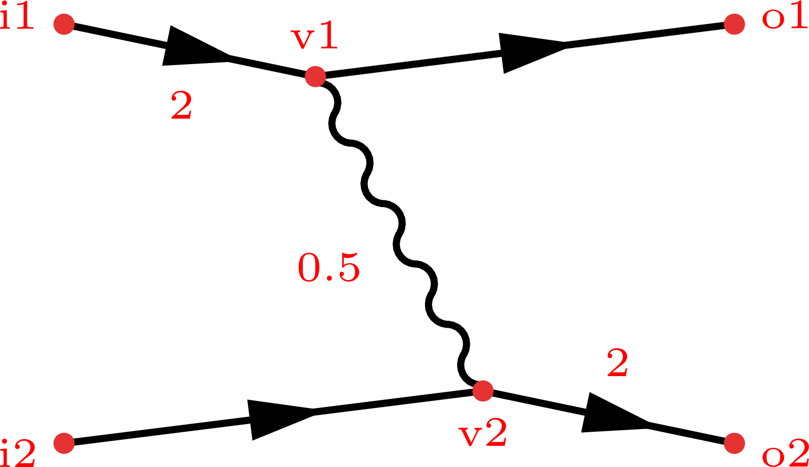
(Note that the figure on the left column has some extra labels highlighter in red for illustrative purposes. Press the big compile button to get the actual result of the code example.)
Internal vertices
Using tension to pull internal vertices
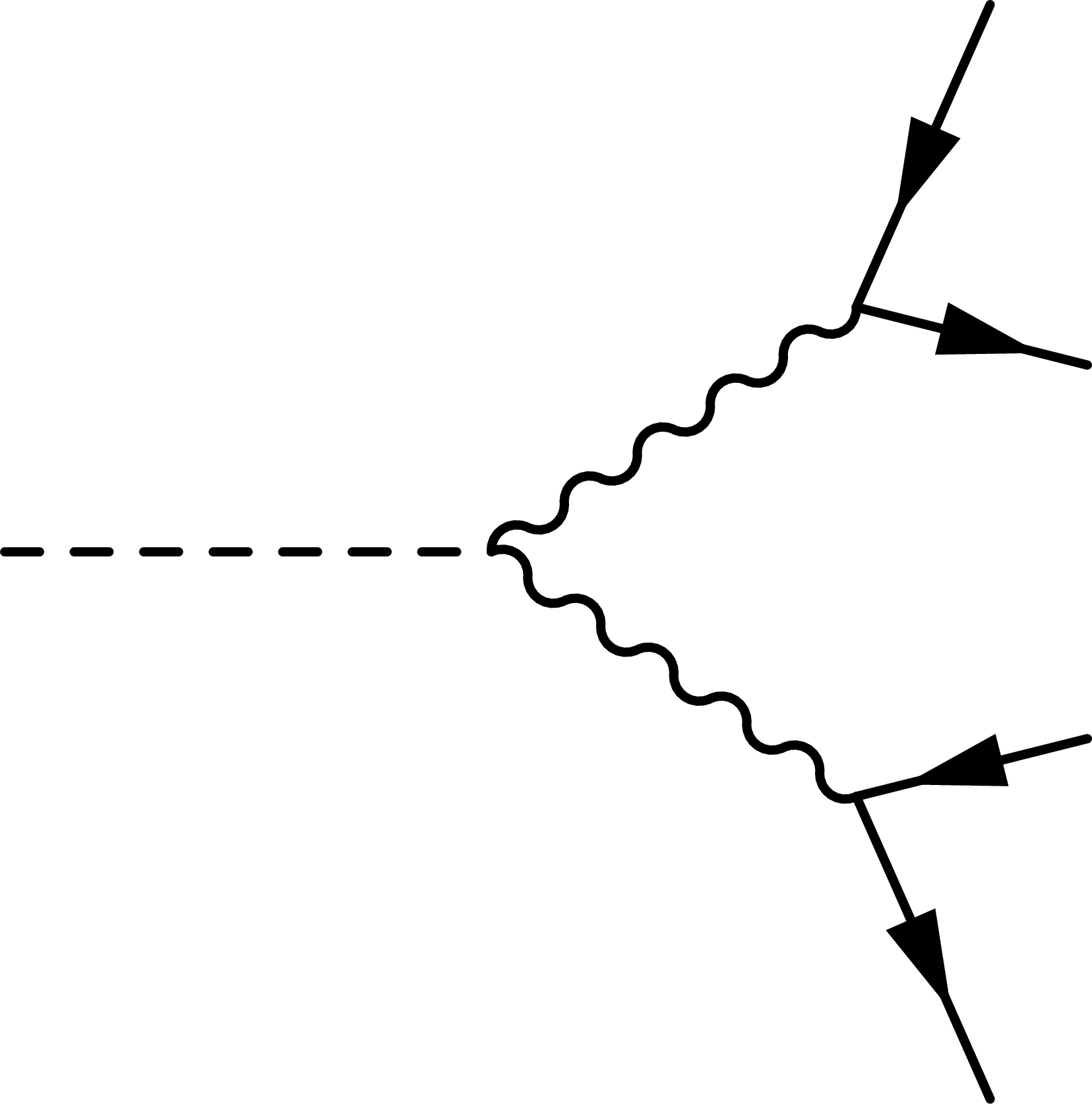
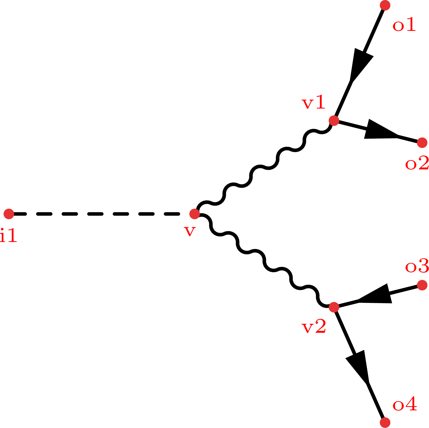
The goal is to make the fermion lines from the boson decay equal in length:
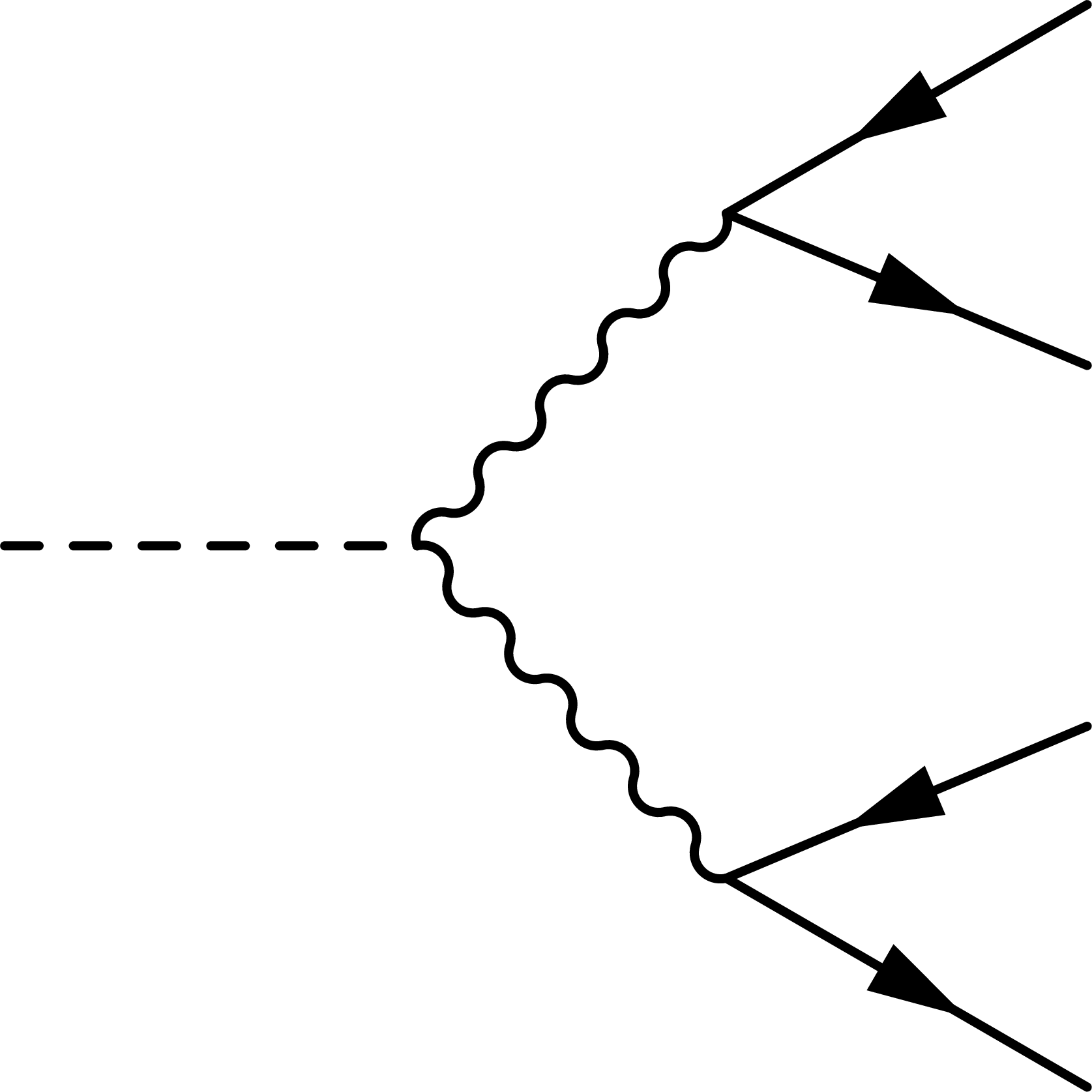
Step 1
\documentclass[11pt,border=4pt]{standalone}
\usepackage{feynmp-auto}
\begin{document}
\begin{fmffile}{feyngraph}
  \begin{fmfgraph*}(120,120) % dimensions (WH)
    % external vertices
    \fmfleft{i1}
    \fmfright{o4,o3,o2,o1}
    % main
    \fmf{fermion}{o1,v1,o2}
    \fmf{fermion}{o3,v2,o4}
    \fmf{dashes,tension=1.5}{i1,v}
    % decay
    \fmf{boson}{v,v1}
    \fmf{boson}{v,v2}
  \end{fmfgraph*}
\end{fmffile}
\end{document}
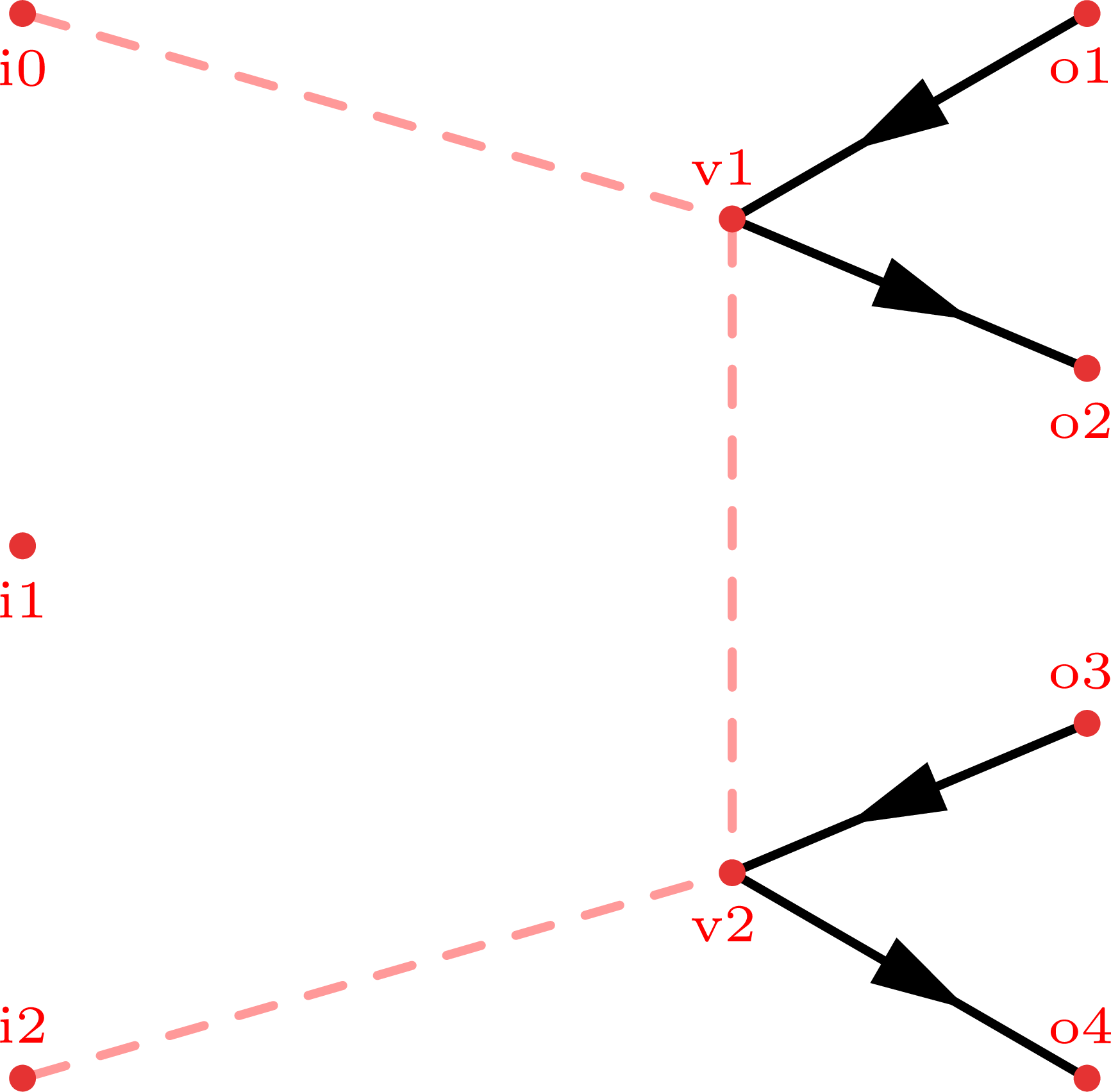
Step 2
\documentclass[11pt,border=4pt]{standalone}
\usepackage{feynmp-auto}
\begin{document}
\begin{fmffile}{feyngraph}
  \begin{fmfgraph*}(120,120) % dimensions (WH)
    % external vertices
    \fmfstraight
    \fmfleft{i2,i1,i0}
    \fmfright{o4,o3,o2,o1}
    % skeleton
    \fmf{dashes,foreground=(1,,.6,,.6)}{i0,v1}
    \fmf{dashes,foreground=(1,,.6,,.6),tension=0.4}{v1,v2}
    \fmf{dashes,foreground=(1,,.6,,.6)}{i2,v2}
    % main
    \fmf{fermion}{o1,v1,o2}
    \fmf{fermion}{o3,v2,o4}
  \end{fmfgraph*}
\end{fmffile}
\end{document}
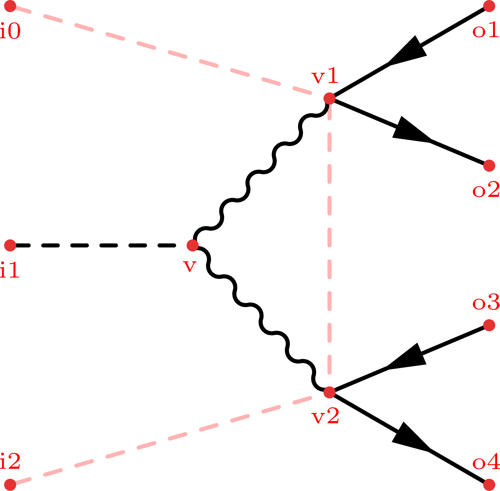
Step 3
\documentclass[11pt,border=4pt]{standalone}
\usepackage{feynmp-auto}
\begin{document}
\begin{fmffile}{feyngraph}
  \begin{fmfgraph*}(120,120) % dimensions (WH)
    % external vertices
    \fmfstraight
    \fmfleft{i2,i1,i0}
    \fmfright{o4,o3,o2,o1}
    % skeleton
    \fmf{dashes,foreground=(1,,.7,,.7)}{i0,v1}
    \fmf{dashes,foreground=(1,,.7,,.7),tension=0.4}{v1,v2}
    \fmf{dashes,foreground=(1,,.7,,.7)}{i2,v2}
    % main
    \fmf{fermion}{o1,v1,o2}
    \fmf{fermion}{o3,v2,o4}
    \fmffreeze
    \fmf{dashes,tension=1.5}{i1,v}
    % decay
    \fmf{boson}{v,v1}
    \fmf{boson}{v,v2}
  \end{fmfgraph*}
\end{fmffile}
\end{document}
Using \fmfforce for exact placement
Full code
The example figures above were generated with the following code: …